High Pressure Test
Bench Part Number: FAS-HPT-1000
(دستگاه تست فشار بالای 1000 bar)
PURPOSE:
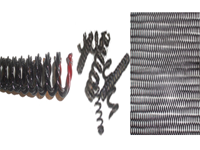
The High Pressure Test Bench, a universal type with pneumatic and hydraulic capabilities, is used to perform functional testing of various type of valves such as non return valve , relief valve ,stop valve and etc, in accordance with their specific procedures.
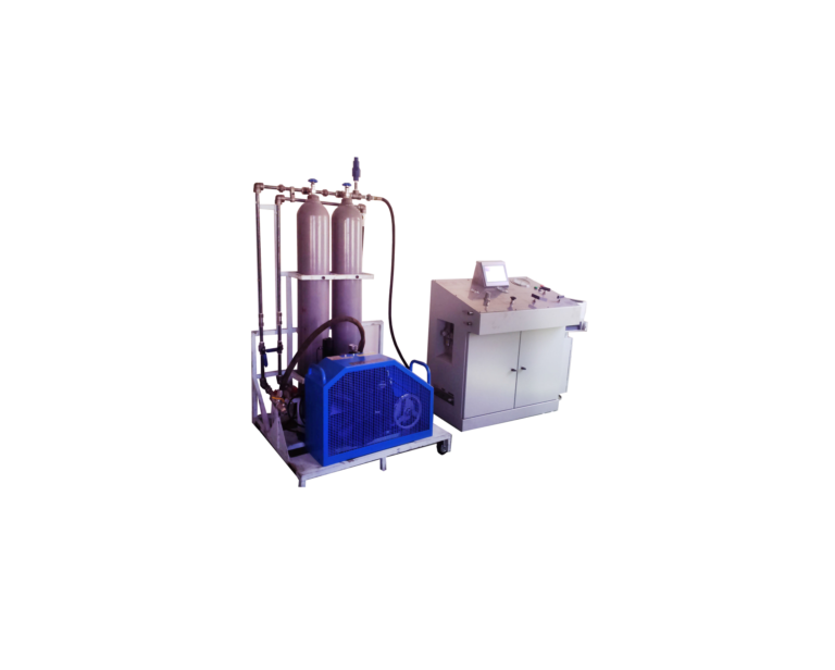
This unit consists of three separately systems: oil system, water system and air system.
LEADING PARTICULAR:
The major specification of the unit are as below:
length …………………………………………….…………………….….…………..1200 mm
Width………….………………………..…………….…………………….…..……..700 mm
Height …….……………………………..……………………………………..……….900 mm
Operating Fluids ……………………………………………………………..….Oil, Water, Air
Power system…………………….…………………..…………………..…….Booster pump
Power………………………………………….….…….…………………….220V,1PH,50HZ
Ambient Temperature .…………………….….…………………..……. Range: 0ºC to 50ºC
Weight (approximate)………..…………………………………………………………150 kg
Oil system:
Operating Fluid ………………………..………………………………………………..….Oil
Operating Pressure (hydraulic)….……………………………15000 psig (1000 bar), max
Gage ………………………………………………….…….………0-1000 bar (15000 psig)
Water system:
Operating Fluid ………………………………….…………………………………..….Water
Operating Pressure (hydraulic)…………………………….… 15000 psig (1000 bar), max
Gage ……………………………………….………..…….………0-1000 bar (15000 psig)
Air system:
Operating Fluid …………………………………………………….…………………..…. Air
Operating Pressure (pneumatic)…………….…………….……..… 100 psig (7 bar), max
Gage ………………………………..…………………..…………………0-7 bar (100 psig)
DESCRIPTION:
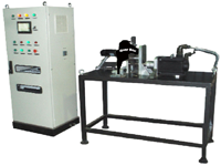
The stationary test bench is highly reliable precision device is designed to perform tests on the hydraulic and pneumatic components, at required pressure. It operates in manual mode.
The test stand is a universal type with hydraulic and pneumatic capabilities. It needs to be connected to a water, a pneumatic and an electrical power source.
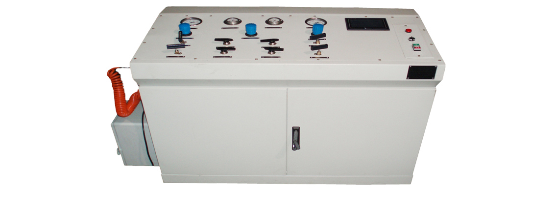
The test stand consists of an integrally assembled metal console, housing, pneumatic, hydraulic and electric controls mounted within the background panel. All controls are arranged for ease of operation and visual monitoring. All tubing and wiring have bulkhead fittings and connectors to facilitate ease of operation.
Screwed panels and hinged doors provide easy access to the different components and, therefore, facilitate maintenance. The different measuring instruments (pressure gages, HMI, . . . ) are located on the control panel.
Two booster pump (motor and pump), a filling pump, check valves, shut off valves, filter & purifier and pressure transducers are located on the control console for producing and controlling the required pressure. The Air filter & purifier is located at the left hand of the control console in the air inlet line.
An electrical box is located at the left hand of the unit included of PLC, power, contactor, fuse and wiring to control and monitor the required pressure. A HMI is provided for monitoring the pressure. This unit is programmed to indicate the oil and water pressure simultaneously and draws their graphs. It is equipped to a printer port for printing the results